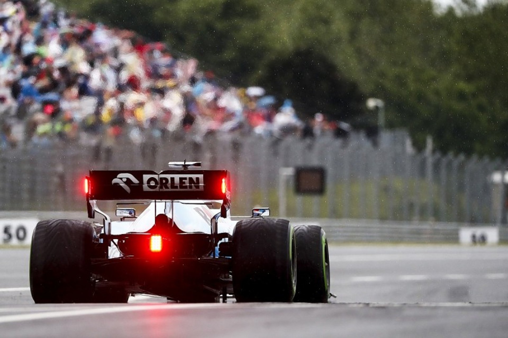
F1 rainlight
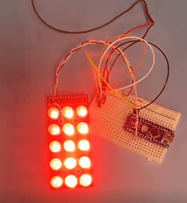
V1- Breadboard
The V1 was created originally on a breadboard and then transferred to veroboard to make the design more stable whilst programming and working on potential housing designs. Originally due to the resources available at the time 3mm LEDs were chosen and the circuit was basic in operation (No Processing).
Pros:
Cheap to fabricate
Simple circuit
allows a base to start working on code for microcontroller.
Cons:
Small LEDs
No Processing
Cannot work on full housing
Learning Points:
+ CAD for laser cutting (.dxf)
+ Soldering Skills
- Need to make a PCB
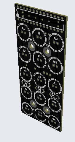
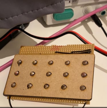
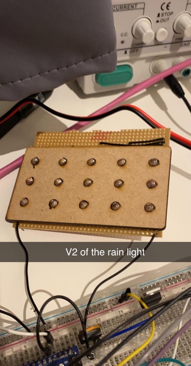
V2- PCB
The V2 was developed to make the design even more stable whilst programming and working on potential housing designs. Again 3mm LEDs were chosen for use, however, this time a PCB was designed to carefully hold all of the components including an Arduino Nano microcontroller. The housing was also developed as there was a known size for the board now which meant 3D models could be generated and tested. Originally the idea was to use a clear rectangle of perspex to protect the LEDs/ Electronics from damage.
Pros:
Contains Microcontroller
Housing designs have started
PCB design completed
Cons:
3mm LEDs
Small Cost and wait time for shipping
requires assembly method for 3 part casing (inc. Screen)
Learning Points:
+ Arduino Programming
+ Soldering Skills
+ PCB Design and Assembly
+3D Modelling/ 3D Printing
-Complex casing
-No power management
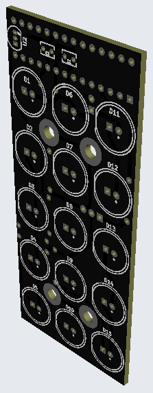
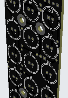
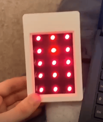
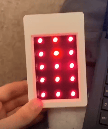
V3- Upgraded PCB
The V3 was designed to improve all of the issues seen with the V2 board, for example, the LEDs were increased from 3mm to 10mm which create a greater brightness. The board also included an Atmega328P which allowed for a more discrete microcontroller than previous iterations. Mounting holes were added to allow easier integration with the housing.
Pros:
LED size increase
Discrete microcontroller
Mounting holes added
Cheaper PCB Price
Cheaper Unit cost (No Arduino!)
Cons:
Microcontroller mounting causes fitment issues
Programming of ATmega328 is awkward
No Power regulation
Learning Points:
+ Improved Microcontroller
+ Soldering Skills
- Need to implement power regulation
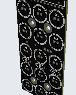
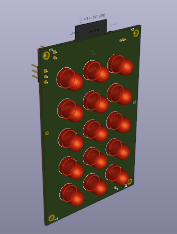
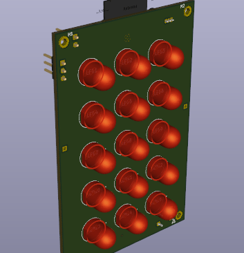
V4- PCB
The V4 was a minimalistic upgrade from V3 with some minor layout changes made to the PCB, the power regulation issue was resolved with the use of a LM317 through-hole component. The board still includes an ATmega328 chip which has huge advantages over the Arduino nano, it is a pain to program and can be easily damaged. The housing changed to accommodate the new design although fundamentally the design remained the same as before. This version included a brake line ability through modification of the board.
Pros:
Power management
Better housing
Cons:
No real mount for the car
Learning Points:
+ Arduino Programming
-Complex casing